Inverse Sinc Finite Impulse Response Filter Design
Keywords: firdespm finite impulse response filter design parks mcclellan inverse sinc
This tutorial explains how to generate an inverse sinc filter in liquid-dsp to compensate for the distortion caused by rectangular (sinc) filters commonly implemented in hardware.
Many digital transceiver implementations use a very basic filter that applies an equal-weighting average to the input samples. From a continuous-time standpoint, the impulse response of such a filter is just a rectangle in time which provides a spectral response that's a sinc function, viz
You don't have to look too hard at the response above to realize that this isn't a very good filter. Specifically it has the following problems:
- The magnitude response isn't very flat in the pass-band
- The first side-lobe is only about 13 dB down from the peak
- The side-lobes taper off very slowly (specifically at a rate \(1/f\) )
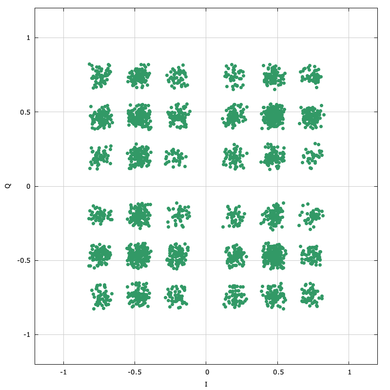
Still, the prospect of such a simple filter is attractive enough for designers to use it. The problem with using such a filter for digital communications is that it distorts the signal in such a way as to cause errors. When this filter is applied to a linear-modulated QPSK signal, the result causes a significant amount of inter-symbol interference and distortion, resulting in an increased error rate. For example the figure below shows the received constellation of a QPSK signal that has experienced a sinc filter whose bandwidth is slightly larger than its modulated bandwith:

Figure [firdespm-sinc-example-const]. Applying the sinc filter to a QPSK signal causes lots if inter-symbol interference and distortion.
One of the Nyquist criteria for a signal with zero inter-symbol interference is for its spectral response to be flat in the pass-band. Clearly the response visible in [ref:firdespm-invsinc-example-sinc] violates this criterion which is why there is so much distortion in the above constellation. What we would like to do is design a filter that we can apply to the signal either before or after the sinc filter to compensate for its effects. liquid-dsp provides a straightforward way to design non-recursve filters with arbitrary responses using the Parks-McClellan algorithm. Specifically the user may define a callback function to define whatever filter response and appropriate weighting function are desired.
For an inverse sinc, we have three particular regions of its frequency response:
- Pass-band response : invert the sinc response (compensate for droop seen in[ref:firdespm-sinc-response-freq] )
- Stop-band response : attenuate as much as possible
- In-between response : don't care (gracefully transition between pass-band and stop-band)
Shown below is a short example program demonstrating how to design the inverse sinc filter:
// firdespm.example.c : example program showing inverse sinc filter generation
// http://liquidsdr.org/blog/firdespm-invsinc/
#include <stdio.h>
#include <math.h>
#include <liquid/liquid.h>

// user-defined callback function defining response and weights
int callback(double   _frequency,   // normalized input frequency, in [0,0.5]
             void   * _userdata,    // user-defined data pointer
             double * _desired,     // output desired response for this frequency
             double * _weight)      // output desired weight for this frequency
{
    // de-reference pointer as floating-point value
    unsigned int n  = *((unsigned int*)_userdata);  // sinc filter length
    double       v  = sincf(n*_frequency);          // sinc response
    double       fc = 1.0f / (float)n;              // first sinc null

    // design filter response
    if (_frequency < fc) {
        // pass-band: inverse sinc
        *_desired = 1.0f / v;
        *_weight  = 4.0f;
    } else {
        // stop-band: reject and scale weight appropriately
        *_desired = 0.0f;
        *_weight  = 10*fabs(v) * exp(4.0*_frequency);
    }
    return 0;
}

int main(int argc, char*argv[])
{
    // options
    unsigned int n     =  7;    // nominal sinc filter length
    unsigned int p     = 24;    // inverse sinc filter semi-length
    unsigned int h_len = 4*p+1; // filter length
    float        h[h_len];      // filter coefficients buffer

    // specify 2 edges for each of the band
    unsigned int num_bands = 2; // pass-band and stop-band
    float bands[4]  = {
        0.00f,          // lower pass-band edge (start at DC)
        0.85f/(float)n, // upper pass-band edge (just below first sinc null)
        1.05f/(float)n, // lower stop-band edge (just above first sinc null)
        0.5f};          // upper stop-band edge (half sample rate)

    // this will be a band-pass filter type
    liquid_firdespm_btype btype = LIQUID_FIRDESPM_BANDPASS;

    // design inverse sinc filter using callback function, storing results in 'h'
    firdespm q = firdespm_create_callback(h_len,num_bands,bands,btype,callback,&n);
    firdespm_execute(q,h);
    firdespm_destroy(q);

    // print coefficients and return
    unsigned int i;
    for (i=0; i<h_len; i++)
        printf("%16.12f\n", h[i]);
    return 0;
}
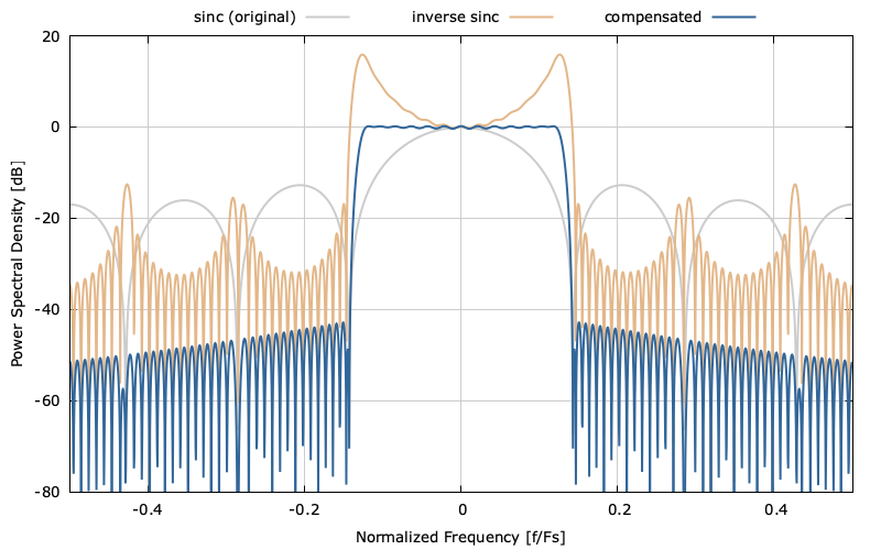
Notice that the the main program defines the pass-band and stop-band regions while the callback function completely defines the response these regions. The weighting function for the stop-band increases exponentially with frequency so that the side-lobes fall off away from the pass-band. Running this program produces a filter with the response showin in the figure below.
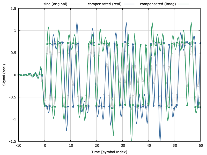
Notice that the inverse sinc filter raises up the edges of the pass-band so that the composite response is relatively flat in this region. The composite stop-band demonstrates a nice spectral roll-off with the side-lobes the further the frequency gets from the main lobe. The time-domain response of the three filters can be seen in the figure below.
The original sinc pulse is shown in the top plot with our filter and the compensated response in the middle and bottom plots respectively. The compensated response is simply the convolution of the top two.
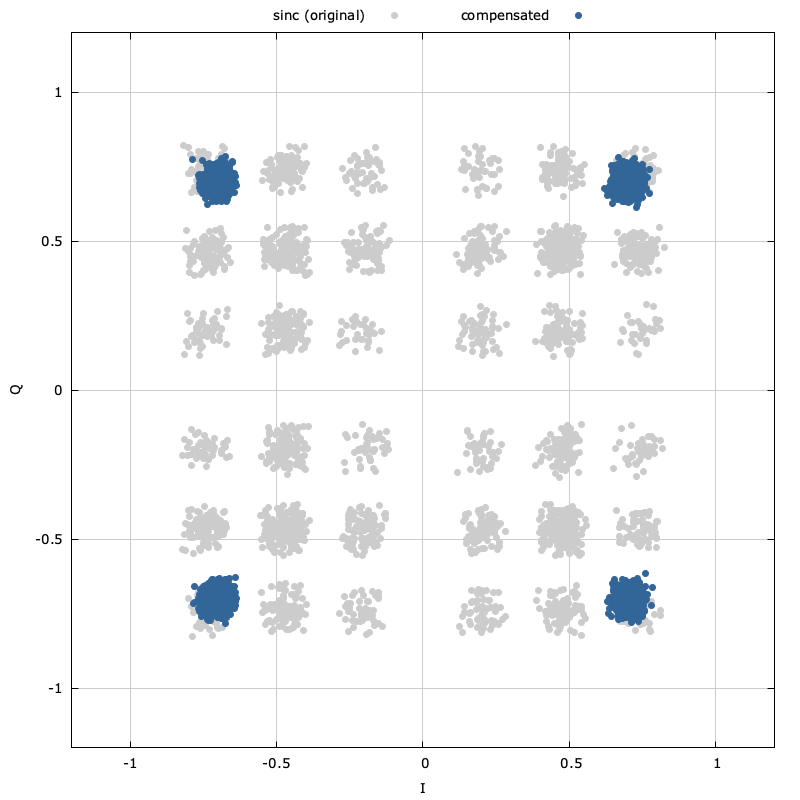
So how does this improve our original QPSK example? Remember that the original sinc filter caused significant distortion to the received constellation. If we apply our inverse sinc compensating filter to the orignal signal we get the following result:

Figure [firdespm-invsinc-example-const]. Constellation diagram before and after \(sinc(f)\) compensation
Notice that the received constellation in [ref:firdespm-invsinc-example-const] while not perfect is significantly improved with the compensating filter than without. Further improvements could be made by increasing the length of the compensating filter and adjusting the pass-band and stop-band weighting functions.
While I have shown how the firdespm method in liquid-dsp with a user-defined callback function can be used for a sinc compensating filter, it can certainly be used for designing a wide variety of filters.


