Automatic Gain Control (agc)
API Keywords: automatic gain control AGC
Normalizing the level of an incoming signal is a critical step in many wireless communications systems and is necessary before further processing can happen in the receiver. This is particularly necessary in digital modulation schemes which encode information in the signal amplitude (e.g. see LIQUID_MODEM_QAM16 in [ref:section-modem-digital] ). Furthermore, loop filters for tracking carrier and symbol timing are highly sensitive to signal levels and require some degree of amplitude normalization.
Theory of Operations∞
As such automatic gain control plays a crucial role in SDR. The ideal AGC has a transfer function as in[ref:fig-agc-transfer-function] . When the input signal level is low, the AGC is disabled and the output is a linear function of the input. When the input level reaches a lower threshold, \(e_0\) , the AGC becomes active and the output level is maintained at the target (unity) until the input reaches its upper limit, \(e_1\) . The AGC is disabled at this point, and the output level is again a linear function of the input.
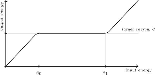
Figure [fig-agc-transfer-function]. Ideal AGC transfer function of input to output signal energy.
liquid implements automatic gain controlling with the agc_xxxt family of objects. The goal is to estimate the gain required to force a signal to have a unity target energy. Operating one sample at a time, the agc object makes an estimate\(\hat{e}\) of the signal energy and updates the internal gain \(g\) , applying it to the input to produce an output with the target energy. The gain estimate is updated by way of an open loop filter whose bandwidth determines the update rate of the AGC.
Given an input signal\(\vec{x} = \{ x_0, x_1, x_2, \ldots, x_{N-1} \}\) , its energy is computed as its \(L_2\) norm over the entire sequence, viz
$$ E\{ \|\vec{x}\| \} = \left[ \sum\limits_{k=0}^{N-1} {\|x_k^2\|} \right]^{1/2} $$For received communications signals, however, the goal is to adjust to the gain of the receiver relative to the slowly-varying amplitude of the incoming receiver due to shadowing, path loss, etc. Furthermore, it is impractical to estimate the signal energy of an entire vector for each sample of input. Therefore it is necessary to make an estimate of the signal energy over a short period of time. This is accomplished by computing the average of only the previous \(M\) samples of \(|x|^2\) ; liquid uses an internal buffer size of \(M=16\) samples. Now that the short-time signal energy has been estimated, all that remains is to adjust the gain of the receiver accordingly. liquid implements an open-loop gain control by adjusting the instantaneous gain value to match the estimated signal energy to drive the output level to unity. The loop filter for the gain is a first-order recursive low-pass filter with the transfer function defined as
$$ H_g(z) = \frac{ \alpha }{ 1 - (1-\alpha) z^{-1} } $$where \(\alpha \triangleq \sqrt{\omega}\) . In order to achieve a unity target energy, the instantaneous ideal gain is therefore the inverse of the estimated signal level,
$$ \hat{g}_{k} = \sqrt{1 / \hat{e}_k} $$Rather than applying the gain directly to the input signal it is first filtered as
$$ g_{k} = \alpha \hat{g}_{k} + (1-\alpha) g_{k-1} $$where again \(\alpha \triangleq \sqrt{\omega}\) is the smoothing factor of the gain estimate and controls the attack and release time the agc object has on an input signal. Because \(\alpha\) is typically small, the updated internal gain \(g_{k}\) retains most of its previous gain value \(g_{k-1}\) but adds a small portion of its new estimate \(\hat{g}_{k}\) .
Locking∞
The agc object permits the gain to be locked when, for example, the header of a frame has been received. This is useful for effectively switching the AGC on and off during short, burst-mode frame transmissions, particularly when the signal has a high-order digital amplitude-modulation (e.g. 64-QAM) and fluctuations in the AGC could potentially result in symbol errors. When the agc object is locked, the internal gain control is not updated, and the internal gain at the time of locking is applied directly to the output signal, forcing \(g_k = g_{k-1}\) . Locking and unlocking is accomplished with the agc_crcf_lock() and agc_crcf_unlock() methods, respectively.
Squelch∞
The agc object contains internal squelch control to allow the receiver the ability to disable signal processing when the signal level is too low. In traditional radio design, the squelch circuit suppressed the output of a receiver when the signal strength would fall below a certain level, primarily used to prevent audio static due to noise when no other operators were transmitting. Having said that, the squelch control in liquid is actually somewhat of a misnomer as it does not actually control the AGC, but rather just monitors the dynamics of the signal level and returns its status to the controlling unit. The squelch control follows six states|enabled, rising edge trigger, signal high, falling edge trigger, signal low, and timeout|as depicted in [ref:fig-agc-squelch] and[ref:tab-agc-squelch-codes] . These states give the user flexibility in programming networks where frames are transmitted in short bursts and the receiver needs to synchronize quickly. The status of the squelch control is retrieved via the agc_crcf_squelch_get_status() method.
The typical control cycle for the AGC squelch is depicted in[ref:fig-agc-squelch] . Initially, squelch is enabled (code 0 ) as the signal has been low for quite some time. When the beginning of a frame is received, the RSSI increases beyond the squelch threshold (code 1 ). All subsequent samples above this threshold return a signal high'' status (code 2 ). Once the signal level falls below the threshold, the squelch returns a falling edge trigger'' status (code 3 ). All subsequent samples below the threshold until timing out return a signal low'' status (code 4 ). When the signal has been low for a sufficient period of time (defined by the user), the squelch will return a timeout'' status (code 5 ). All subsequent samples below the threshold will return a squelch enabled'' status.
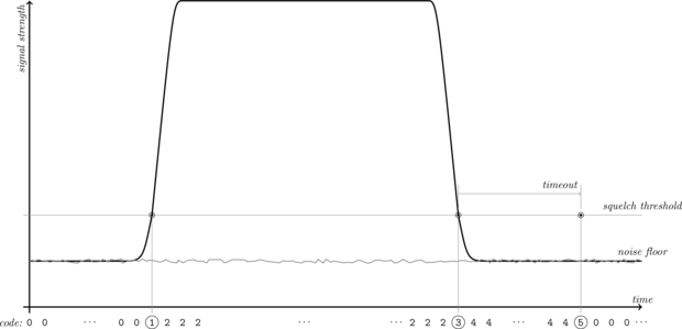
Figure [fig-agc-squelch]. agc_crcf squelch
Table [tab-agc-squelch_codes]. AGC squelch codes, numerical values, and description
| Code | ID | Description |
| 0 | LIQUID_AGC_SQUELCH_ENABLED | squelch enabled |
| 1 | LIQUID_AGC_SQUELCH_RISE | rising edge trigger |
| 2 | LIQUID_AGC_SQUELCH_SIGNALHI | signal level high |
| 3 | LIQUID_AGC_SQUELCH_FALL | falling edge trigger |
| 4 | LIQUID_AGC_SQUELCH_SIGNALLO | signal level low, but no timeout |
| 5 | LIQUID_AGC_SQUELCH_TIMEOUT | signal level low, timeout |
Methodology∞
The reason for all six states (as opposed to just squelch on'' and squelch off'') are to allow for the AGC to adjust to complex signal dynamics. The default operation for the AGC is to disable the squelch. For example if the AGC squelch control is in signal low'' mode (state 4 ) and the signal increases above the threshold before timeout, the AGC will move back to the signal high'' mode (state 2 ). This is particularly useful for weak signals whose received signal strength is hovering around the squelch threshold; it would be undesirable for the AGC to enable the squelch in the middle of receiving a frame!
auto-squelch∞
The AGC module also allows for an auto-squelch mechanism which attempts to track the signal threshold to the noise floor of the receiver. This is accomplished by monitoring the signal level when squelch is enabled. The auto-squelch mechanism has a 4dB headroom; if the signal level drops below 4dB beneath the squelch threshold, the threshold will be decremented. This is useful for receiving weak signals slightly above the noise floor, particularly when the exact noise floor is not known or varies slightly over time. Auto-squelch is enabled/disabled using the agc_crcf_squelch_enable_auto() and agc_crcf_squelch_disable_auto() methods respectively.
Interface∞
Listed below is the full interface to the agc family of objects. While each method is listed for the agc_crcf object, the same functionality applies to the agc_rrrf object.
- agc_crcf_create() creates an agc object with default parameters. By default the minimum gain is \(10^{-6}\) , the maximum gain is \(10^6\) , the initial gain is \(1\) , and the estimate of the input signal level is \(0\) . Also the AGC type is set to LIQUID_AGC_DEFAULT .
- agc_crcf_destroy(q) destroys the object, freeing all internally-allocated memory.
- agc_crcf_print(q) prints the agc object internals to stdout .
- agc_crcf_reset(q) resets the state of the agc object. This unlocks the AGC and clears the estimate of the input signal level.
- agc_crcf_set_gain_limits(q,gmin,gmax) sets the minimum and maximum gain values, respectively. This effectively specifies \(e_0\) and \(e_1\) as in[ref:fig-agc-transfer-function] .
- agc_crcf_lock(q) prevents the AGC from updating its gain estimate. The internal gain is stored at the time of lock and used for all subsequent occurrences of agc_crcf_execute() . This is primarily used when the beginning of a frame has been detected, and perhaps the payload contains amplitude-modulated data which can be corrupted with the AGC aggressively attacking the signal's high dynamics. Also, locking the AGC conserves clock cycles as the gain update is not computed. Typically, the locked AGC consumes about \(5\times\) fewer clock cycles than its unlocked state.
- agc_crcf_unlock(q) unlocks the AGC from a locked state and resumes estimating the input signal level and internal gain.
- agc_crcf_execute(q,x,y) applies the gain to the input \(x\) , storing in the output sample \(y\) and updates the AGC's internal tracking loops (of not locked).
- agc_crcf_get_signal_level(q) returns a linear estimate of the input signal's energy level.
- agc_crcf_get_rssi(q) returns an estimate of the input signal's energy level in dB.
- agc_crcf_get_gain(q) returns the agc object's internal gain.
- agc_crcf_squelch_activate(q) activates the AGC's squelch module.
- agc_crcf_squelch_deactivate(q) deactivates the AGC's squelch module.
- agc_crcf_squelch_enable_auto(q) activates the AGC's automatic squelch module.
- agc_crcf_squelch_disable_auto(q) deactivates the AGC's automatic squelch module.
- agc_crcf_squelch_set_threshold(q,t) sets the threshold of the squelch.
- agc_crcf_squelch_set_timeout(q,t) sets the timeout (number of samples) after the signal level has dropped before enabling the squelch again.
- agc_crcf_squelch_get_status(q) returns the squelch status code (see [ref:tab-agc-squelch-codes] ).
Here is a basic example of the agc object in liquid:
#include <liquid/liquid.h>

int main() {
    agc_crcf q = agc_crcf_create();     // create object
    agc_crcf_set_bandwidth(q,1e-3f);    // set loop filter bandwidth

    float complex x;                    // input sample
    float complex y;                    // output sample

    // ... initialize input ...

    // repeat as necessary
    {
        // scale input sample, storing the result in 'y'
        agc_crcf_execute(q, x, &y);
    }

    // clean it up
    agc_crcf_destroy(q);
}
A demonstration of the transient response of the agc_crcf type can be found in [ref:fig-agc-transient] in which an input complex sinusoidal pulse is fed into the AGC. Notice the initial overshoot at the output signal.
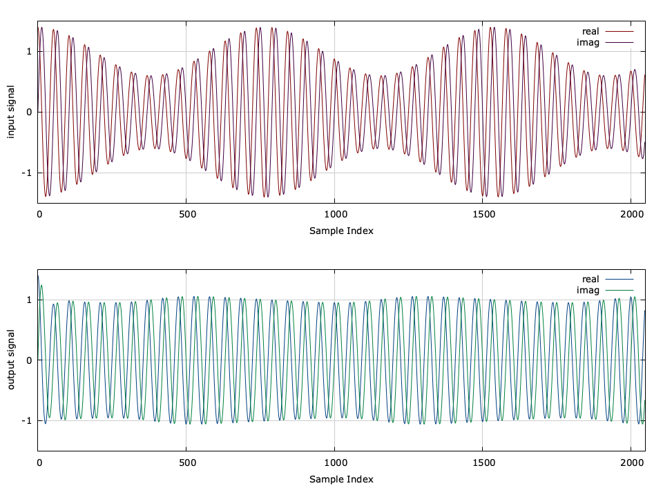
Figure [fig-agc-transient]. agc_crcf transient response
A few more detailed examples can be found in the examples subdirectory.